Technical understanding part 3
Jump to navigation
Jump to search
Contents
- 1 6.4c Interfacing electronic circuits with mechanical and pneumatic systems and components
- 2 6.4d Demonstrate an understanding of networking and of communication protocols, such as:
- 3 6.4e Demonstrate an understanding of the basic principles of electricity, including:
- 4 6.5a Demonstrate an understanding of how smart materials change the functionality of engineered products, such as:
- 5 6.5b Demonstrate an understanding of how programmable devices are used to add functionality to products, relating to coding of and specific applications of programmable components, such as:
6.4c Interfacing electronic circuits with mechanical and pneumatic systems and components
Electronic Control for inputs
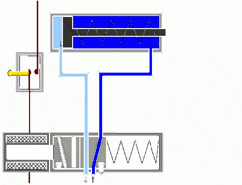
- Electronic control can be used as an input to mechanical or pneumatic output. Watch the video below, which shows the basics of electro-pneumatics.
- Tip: A detailed guide to pneumatics which includes everything you need to know can be downloaded here.
- In a pneumatic circuit, restrictor valves can be used to control cylinder speed by slowing the speed at which air can travel through an air-line. To read more about flow restrictors and the many different types and how they work, click here.
Exam style question:
An engineer wishes to design a system to bend a aluminium bar 30 degrees using pneumatic cylinders and valves. They are concerned for the operator’s safety, so wish to ensure that they place both hands on push actuators before the cylinder is activated in order to ensure their hands are not accidentally crushed.
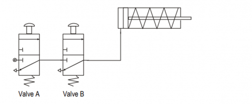
Sketch a system which will send a single-acting cylinder positive (extend) slowly when two push actuators are pushed at the same time. As soon as either actuator (or both actuators) is released, the cylinder should immediately go negative (retract) slowly. [6 marks]
- This solution requires an AND configuration, see image below:
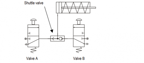
- Here is an example of an OR configuration:
Sensors to measure rotational speed
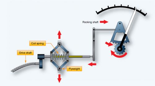
- There are a number of ways to measure rotational speed, the most common being an instrument called a tachometer. A tachometer (revolution-counter, tach, rev-counter, RPM gauge) is an instrument measuring the rotation speed of a shaft or disk, as in a motor or other machine. The device usually displays the revolutions per minute (RPM) on a calibrated analogue dial, but digital displays are increasingly common - you can see tachometers in the rev-counter in a car. In the diagram below, you can see that as the input rotates faster, the fly-weights are spun faster and the resulting force causes the coil-spring to be increasingly compressed. This leads to the output 'needle' moving further to the right.
- You can create your own instrument to measure rotational speed in a lab, such as:
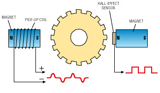
- Electro-magnetic systems. A small magnet can be mounted on a disc connected to a rotating shaft. A reed switch can be placed in the path of the magnet so that once per revolution, the switch is closed momentarily as it passes. This can be connected to a microcontroller which can count the number of times the switch is closed per minute and display this to the end-user. As this approach uses a mechanical part (the reed switch) which takes a few milliseconds to open and close, the system won't be able to accurately record very high speed rotation.
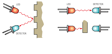
- The use of an LED near a photo-detector (e.g. LDR or phototransistor) with a slotted shaft between them. Every time the shaft rotates to allow light to shine onto the detector, this can be read by a microcontroller and used to accurately count rotational speed (right-hand side of picture below).
Sensors to measure strain/force
- The resistance of a strain gauge changes when force is applied and this change will give a different electrical output (read more here). Strain gauges use this method to measure pressure, force, weight and tension. They are commonly used to measure stress on railway lines and for testing structural components for bridges and buildings.
- These are sometimes integrated into load cells, which can be used to weigh heavy objects.
Sensors to measure distance
- An ultrasonic distance sensor can be used to measure objects up to around 3m away. These work by producing an ultrasonic 'click'. As we know the speed of sound, the time taken for the click to bounce off the surface being measured and for its echo to be detected can then be used to calculate the distance.
- IR distance sensors can be used over shorter ranges (up to about 80cm), and can also approximate distance. As sunlight can interfere with their operation, they can't be used in bright conditions.
- You can read more about distance sensors here.
6.4d Demonstrate an understanding of networking and of communication protocols, such as:
- A network consists of two or more devices connected together so they can exchange data. E.g. A set of 30 PCs in a classroom can be networked so that everyone can access the same printer as well as files from a shared location. The Internet is a large international network, allowing devices all over the world to exchange information stored on web-pages.
- A protocol is an agreed method for communications between devices in a network.
- Serial communication is a protocol to transmit data one bit (a bit is a single 1 or 0) from one device to another. E.g. between two PIC chips.
- TCP/IP (Transfer control Protocol/Internet Protocol) is used to enable communications over the Internet.
- SMTP (Simple Mail Transfer Protocol) is used for the sending of email.
- FTP (File Transfer Protocol) is a protocol used for transferring files from one computer to another over the web.
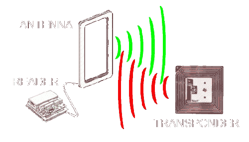
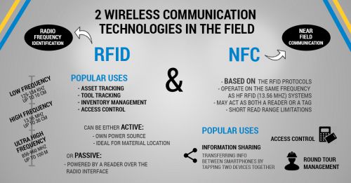
- Radio-frequency identification (RFID) Works when a very small microchip (e.g. inside a ticket, a sticker or under a packaging label on food purchased in a supermarket) receives power by electromagnetic induction from a radio frequency field generated by the reader unit, and it responds by sending a unique identifier code by radio back to the reader unit. Unlike a barcode, the tag need not be within the line of sight of the reader, so it may be embedded in the tracked object.
- Near-field communication (NFC) Similar to RFID in which data is transferred through a short range (4cm) radio field. NFC tickets can be passive (they receive energy from the radio field) or active such as a mobile phone running a payment app.
- Bluetooth is a wireless technology standard for exchanging data over short distances (up to 2-3m reliably) from fixed and mobile devices, and building personal area networks (PANs). In order to exchange data, the devices first need to be 'paired'. This is commonly used in mobile phones for connecting to speakers (e.g. to stream music and car-kits to import contacts/connect to the web).
- Wi-Fi most commonly uses the 2.4 gigahertz and 5GHz radio bands. Anyone within range with a wireless modem can attempt to access the network; because of this, Wi-Fi is more vulnerable to attack than wired networks. Wi-Fi Protected Access (WPA2) is a security technology created to protect information moving across Wi-Fi networks by encrypting data that is transmitted to prevent malicious 3rd parties from reading it.
- Embedded devices are computer systems integrated into a product. It is embedded as part of a complete device often including hardware and mechanical parts. Embedded systems control many devices in common use today, such as calculators and microwave ovens.
- Smart Objects are those which have sensors and microcontrollers installed, often with networking features to enable 2-way communications. E.g. a Smart fridge can have an integrated screen showing a family's calendar, using data taken from their smartphones. A smart printer could order more ink cartridges for itself when it detects that they need to be replaced. A smart home thermostat could communicate with your phone to know when you're on your way home and put the heating on for you automatically.
- Integrated Circuit Card or IC e-card Similar to RFID, but these cards are self-powered and rechargeable.
- Barcodes Every barcode contains a unique identifier code printed as a series of vertical lines. This is read by an optical laser scanner when the barcode is held over the scanner window.
- Quick Response (QR) Code Similar to a barcode but in 2D allowing much more data to be stored and then transferred during the scanning process.
6.4e Demonstrate an understanding of the basic principles of electricity, including:
- Voltage (also called potential difference) is the difference in electric potential between two points. The voltage between two points is equal to the work done per unit of charge against a static electric field to move a test charge between two points. This is measured in units of volts (a joule per coulomb); moving 1 coulomb of charge across 1 volt of electric potential requires 1 joule of work.
- Current is a flow of electric charge. In electric circuits this charge is often carried by moving electrons in a wire. It can also be carried by ions in an electrolyte, or by both ions and electrons such as in an ionised gas (plasma). The SI unit for measuring an electric current is the ampere (amp), which is the flow of electric charge across a surface at the rate of one coulomb per second. Electric current is measured using a device called an ammeter. Electric currents cause Joule heating, which creates light in incandescent light bulbs. They also create magnetic fields, which are used in motors, inductors and generators. The moving charged particles in an electric current are called charge carriers. In metals, one or more electrons from each atom are loosely bound to the atom, and can move freely about within the metal. These conduction electrons are the charge carriers in metal conductors.
- Ohm's law states that the current through a conductor between two points is directly proportional to the voltage across the two points. Introducing the constant of proportionality, the resistance, one arrives at the usual mathematical equation that describes this relationship: V = I X R
- Power is the rate, per unit time, at which electrical energy is transferred by an electric circuit. The SI unit of power is the watt, one joule per second. Electric power is usually produced by electric generators, but can also be supplied by sources such as electric batteries. It is usually supplied to businesses and homes by the electric power industry through an electric power grid. Electric power is usually sold by the kilowatt hour which is the product of power in kilowatts multiplied by running time in hours. Electric utilities measure power using an electricity meter, which keeps a running total of the electric energy delivered to a customer. Electrical power provides a low entropy form of energy and can be carried long distances and converted into other forms of energy such as motion, light or heat with high energy efficiency.
6.5a Demonstrate an understanding of how smart materials change the functionality of engineered products, such as:
- A smart material has a property which reacts in response to a stimulus. This may lead to colour changes, shape-shifting, motion control, self-cleaning or self-healing. For a more detailed list of smart materials, click on this link.
- Possible materials may include:
- Thermochromic pigment is coloured at low temperature but loses its colour above a transition temperature. For instance, in a battery tester, a thin conductive strip heats up when current is passed through it and this heats the thermochromic material. The conductive strip is tapered, so for low currents it only heats the thermochromic pigment at one end, revealing red ink behind, whilst at higher currents it heats the entire length of strip, revealing red, yellow and green ink. Thermochromic pigment is also used in baby feeding products, such as bowls, cups and spoons. These products are made of polymers mixed with thermochromic pigments that change colour with heat, allowing the user to check the temperature, without contaminating the food by touching it.
- Photochromic pigment changes colour in response to light levels. Lenses in glasses can be coated in a photochromic pigment to make them 'reactive'. When the wearer goes outside in bright sunshine, the pigment reacts to the light by becoming coloured, effectively turning the glasses into sunglasses.
- Electroluminescent materials emit light when an electric current passes through them. This is used commonly with back-lit LCD panels, light-up wristwatches or sometimes on car dashboard instruments where a thin film is placed over the surface to be illuminated to help the user read displays in dark conditions.
- Piezoelectric materials are commonly seem in piezo transducers. Compressing certain crystals such as quartz causes electricity to flow through them. The reverse is also true: if you pass electricity through the same crystals, they "squeeze themselves" by vibrating back and forth. One application is for switches (e.g. in an electric drum kit or charity boxes where coins dropped in strike a piezo transducer after a short fall), where striking the transducer triggers an input than can be detected by a microcontroller to trigger an action. The other piezoelectric effect can be used to make very small speakers such as in a musical birthday card, energising a transducer at high frequencies in order to produce sound.
- Shape memory alloy (sometimes known as Nitinol) are metals which are able to 'remember' their original shape and return to it when deformed. This has been used for making glasses frames which can be deformed and will automatically return to their original shape. There are also bioengineering applications such as dental wires such as those used in dental braces and mending broken bones using metal plates.
- Shape memory polymer materials can be deformed. By applying a stimulus, such as heat or light, will return to its previous shape. This could be used to create wrinkle-free, anti-shrinkable and crease retention fabrics. In robotics, shape memory foams are used to provide a soft grip when gripping objects. Foams can be cooled to harden and make a shape adaptive grip.
- Motion control grease regulates the movement of components in contact to provide the right 'feel' or desirable characteristics. Soft-close toilet seats/cupboard doors, sliding microscope barrels and slow spring-return Blu-Ray drawers all incorporate motion control gels.
- Electrochromic material (privacy glass). Electrochromic windows are used in airliners, by the use of suspended particle device (SPD) glass films which provide active shading, applied between the double glazing. When off (no voltage) the particles are scattered creating opacity, as voltage is increased by the user pressing a button, the particles align and light can pass through the window. Similarly, electrochromic glass, known as privacy glass is used in shower and bathrooms; these switch from transparent to opaque when a voltage is applied to them. When the voltage is applied, the liquid crystals inside the glass align and allow light to pass through. When the voltage is nor present the liquid crystal molecules are positioned randomly and block out any light, becoming opaque (private).
6.5b Demonstrate an understanding of how programmable devices are used to add functionality to products, relating to coding of and specific applications of programmable components, such as:
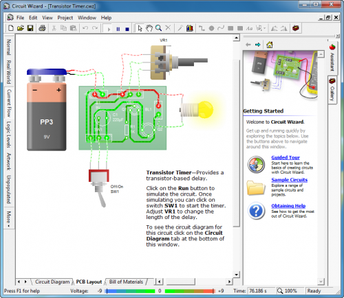
- We use Circuit Wizard to complete all of the tasks below. You will have used the program to develop you own project, from storing data in a variable, to running the program, in the Circuit Wizard virtual environment.
Incorporating enhanced features that can improve the user experience and solve problems
- When using programmable devices, it is possible to create functionality that could not be achieved simply by using discreet components. Loops, IF statements and variables can be used to produce systems such as robotic parts that can make decisions based on different inputs. E.g. A robot arm could be made to sort different parts based on their colour, or a robot vaccuum system could be created to run around a room in a random pattern, hitting walls and changing direction until all of the room is clean.
Basic techniques for measuring, controlling, storing data and displaying information
- Data can be measured by connecting sensors to a PIC input pin - these can be either digital (i.e. capable of being in a finite number of states, like a switch) or analogue (able to hold an infinite number of values in a given range). Common input components are:
- Push-to-Make (PTM) switches. A digital component which allows current to flow into an input pin when the switch is pressed.
- Push-to-Break (PTB) switches. A digital component which stops current from flowing into an input pin when the switch is pressed.
- Light Dependent Resistor (LDR). An analogue component whose resistance increases from about 400 Ohms to 2 million Ohms as it gets darker.
- Potentiometer. An analogue component that is rotated through about 270 degrees, with increasing resistance. Used commonly for volume knobs on amplifiers.
- Output devices can be controlled by connecting them to a microcontroller output pin. Most microcontrollers can only deliver about 25mA from their output pins, so cannot 'drive' components that require more current. Where larger components (e.g. motors) are to be used, either transistors or dedicated driver chips can be used. Common components are:
- LEDs, which can light up when the output pin is energised
- Buzzers, which produce a sound when turned on. As these need about 100mA to operate, they need to be connected via a transistor to ensure they can work correctly.
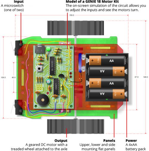
- DC motors, which rotate continuously when energised. As these need about 1000mA (1A) to operate, they need to be connected via a transistor to ensure they can work correctly. These are used for driving small buggies or powering fans. The down-side of using a DC motor is that it is not possible to know how many times the motor has rotated, making these less ideal for applications where precise motion is required (e.g. robot arms).
- To store information, microcontrollers can store data in variables. The Genie microcontrollers that we use in school store these values in locations labelled as letters A,B,C...J. This could be used to build a drawer alarm, when the project is placed in a drawer, it could store the value of the analogue input (the light level) and then compare it until more light is present, thus setting off the alarm. A variable could be created to store a random number as part of an electronic dice project.
- To display information, there are a number of options available to engineers. Some of the most common are:
- LEDs. These can be installed into panels, with labels near them (e.g. 'power'). When the LED is illuminated, the user knows what is happening in the system.
- 7-segment displays are sets of 7 LEDs (8 if you include the decimal point) inside a plastic shape, which shows individual segments of a number. By turning on the different LEDs, numbers can be shown to the user.
- LCD displays. These need a microcontroller to operate. LCDs are able to show several characters of text/numbers on multiple rows, but not graphics. Common sizes are 16x2 and 20x4 characters. The 16x2 units work with Circuit Wizard.
- OLED displays. More complex than an LCD, these need to be used with a more powerful PIC such as an Arduino. These provide high-resolution graphics such as graphs or shapes in addition to text, but require additional programming to make them work. While smartphone and TV displays are full-colour, hobbyist displays such as the ones we get in school tend to be single-colour.
- TFT displays. Similar to OLED displays, but these are able to render graphics in full colour.
Prototyping platforms
- Prior to designing a PCB and etching it, engineers will make prototypes first to ensure that their ideas will work.
- One approach is to build a breadboard using actual components. This will be certainty that your idea will work, but it has a number of draw-backs:
- You may not already have all the components you wish to use
- You are likely to destroy some components if you mis-wire them while you develop your circuit, necessitating the purchase of additional gear
- It is slow and fiddly to create a breadboard. More complex circuits always have the risk of wires not quite making good connections, leading to delays in development
- Electronic prototyping platforms and IDEs for simulation in virtual environments help with this.
- An IDE (integrated development environment) is a set of software that performs multiple functions.
- E.g. Circuit Wizard allows for circuit design, programming, simulation of the circuit/code, PCB design and uploading of code to microcontrollers.
- E.g. Arduino allows for coding and debugging of code, as well as uploading of code and debugging through it's serial monitor.
- We can prototype most circuits needed in school using Circuit Wizard, these prototypes can then be tested in the virtual environment. You need to be careful, as this is a virtual environment, the components will not always act exactly as they would in the 'real' world.
- The use of programmable components and microcontrollers found in products and systems such as robotic arms or cars. This would be the same as above, you will need to start using motors to control robotic arms. Different types of motors are discussed earlier in principle 7. As a recap, these would usually be servo motors or stepper motors which offer accurate rotary movement.
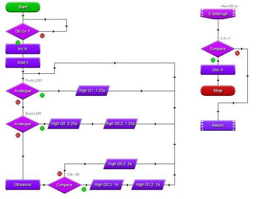
- Creating flowcharts to describe processes and decisions within a process to control input and output components. You have created many flowchart in Circuit Wizard, but you can create flowcharts to explain nearly any situation. Flowcharts are ways to graphically display a process. Flowcharts display steps using the following blocks (there are many more):
- Terminators
- Inputs/outputs
- Decision
- Process
- Directional arrows
